

Cathodic protection
In this section you can find everything you need to know about cathodic protection, both for manual measurements and remote monitoring solutions.
0. Introduction
This section describes how the Withthegrid asset monitoring platform can be applied to Cathodic protection (CP).
Steel pipelines are protected against corrosion through cathodic protection. The cathodic protection needs to be maintained. This means that the voltage and current need to be within the defined boundary. With this remote monitoring device the voltage and current can be measured on a continuous basis. As a result damages and degradation is detected earlier, operational costs are reduced and asset lifetime is increased.
To read more about cathodic protection please read our blog post.
.DPbpjVlp_G8CbA.png)
CP data model
The Withthegrid data model supports the CP hierarchy in the following manner:
| Cathodic protection | Withthegrid name |
|---|---|
| Measurement point | Port |
| Test point (consists of multiple measurements points) | Location (consists of multiple ports) |
| CP system (consists of multiple test points) | Group (consists of multiple locations) |
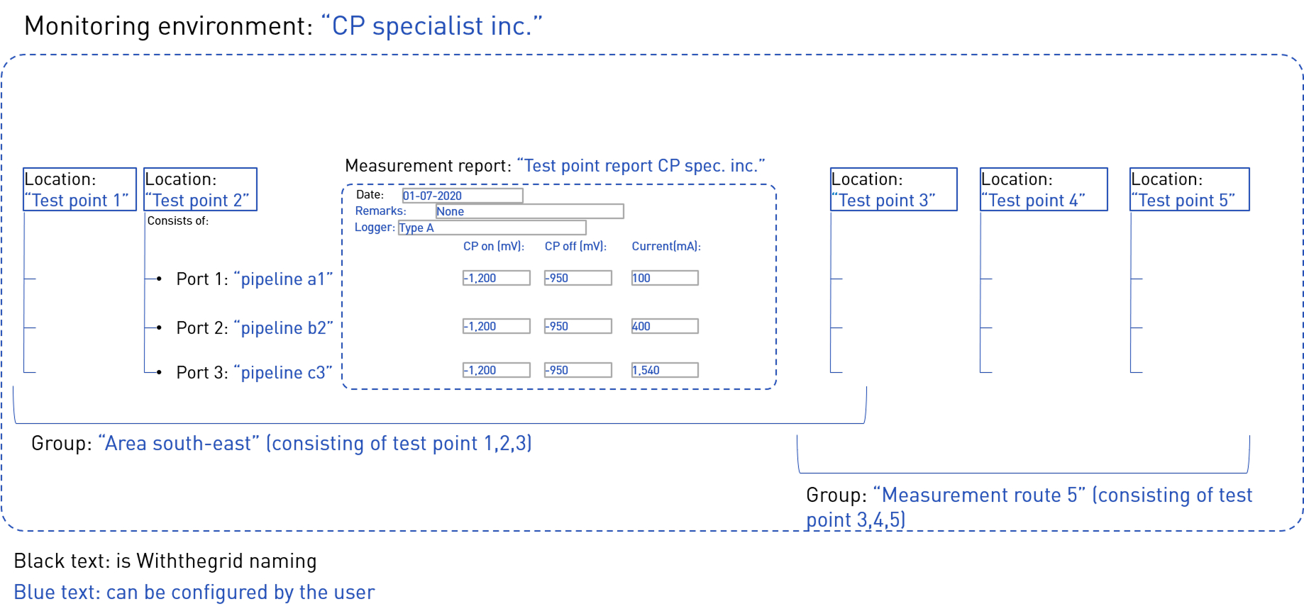
An example of how this may look is shown here:
1. Manual measurements for cathodic protection
One of the functions of the Withthegrid asset monitoring platform is to be able to manage manual cathodic protection measurements from test points, rectifiers etc.
Creating a location
You can create a location by clicking on the map (see below). There are special Cathodic protection icons you can select: rectifier, cathodic protection pole, anode, insulation coupling, AC drain, DC drain, etc.
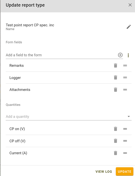
Creating a CP measurement report
You can design your own CP report by constructing a report type. For a general explanation see Condition report types. You can include any quantity you like, some examples are shown below.
- Quantities:
- Voltage DC on
- Voltage DC off
- Voltage AC
- Current
- Frequency
- etc.
- Other items
- Attachments (e.g. DCVG images, picture of the asset condition)
- Error codes
- Remarks
- Logger used
- Last calibration date
- etc.
The user who created the report is automatically stored as well the timestamp of the report. The latter can also be changed manually.
Creating a group
A group consists of multiple locations such as one or more rectifiers, CP test points and drains. To see how to add a group go to groups. A location can be part of multiple groups. Therefore you can create a group to represent a CP system but also a group to represent a manual measurement route.
Creating a manual measurement route
Once you have created a group you can order the locations in the group to create a manual measurement route. The advantage is that you can then visit the test points in the most optimal order.
Map layers
Each location and pipeline can be assigned to a specific map layer. This way you can view on the map:
- Only test points with a remote monitoring device
- Only test points
- Only rectifiers
Map layers can be configured any way you like.
User rights
Ofcourse you can determine which user can do what. For example some users may only be allowed to view CP reports. Some users may be allowed to change the locations and enter manual measurements. See Users on how to configure this.
2. Remote monitoring by device - general section
Device types
There are two main remote monitoring device types for cathodic protection:
- Cathodic protection analog rectifier
- Cathodic protection pole (newest model is Cathodic protection (3x voltage, 1x current))
Additionally, there is a device type that can control specific rectifiers of the brand Amstel:
Device installation
Ideally, the device connectivity is tested before installation, to make sure data can be transmitted to the platform, see this section for more information.
Next, the CP remote monitoring device has to be installed, we will dive into that further below.
Finally, to link a CP remote monitoring device, which you have installed in the field, follow the instructions that can be found under IoT Device. In short, the steps are:
- Create or find the location you want to attach the device to
- Link the device to the location
- Switch on the device and verify installation by checking the data comes in
For battery-powered devices, such as the CP (3x voltage, 1x current) device, is important to not switch on the device for too long before linking it to the platform. The reason is that upon establishing connection with the platform, commands are sent to the device to manage its measurent cycle interval.
Antenna installation
General information on installing the antenna can be found here.
Standard commands sent to devices upon linking to the platform
Upon linking the device to the platform a few commands are sent to the device. These are to ensure that the device is calibrated and that it is set to the desired measurement interval.
For battery-powered devices it’s very important these commands are sent. They decrease the measurement cycle from once every 5 minutes to once every day, for example, to save battery time.
For each single device Withthegrid will set the desired measurement cycle the device will end up with in the end. This will be dependent on the wishes of the customer, but generally it’s set to every day or every week.
The first command is always to start measuring every 5 minutes, this helps the installer to verify all measurements are coming in and are correct.
For standard commands per device type, look under that device type section.
Cellular signal strength
Cathodic protection devices use the 4th generation network connection LTE-M Cat1. The device strength is recorded and passed on to the platform in the quantity RSSI (dBm).
3. Cathodic protection analog rectifier device
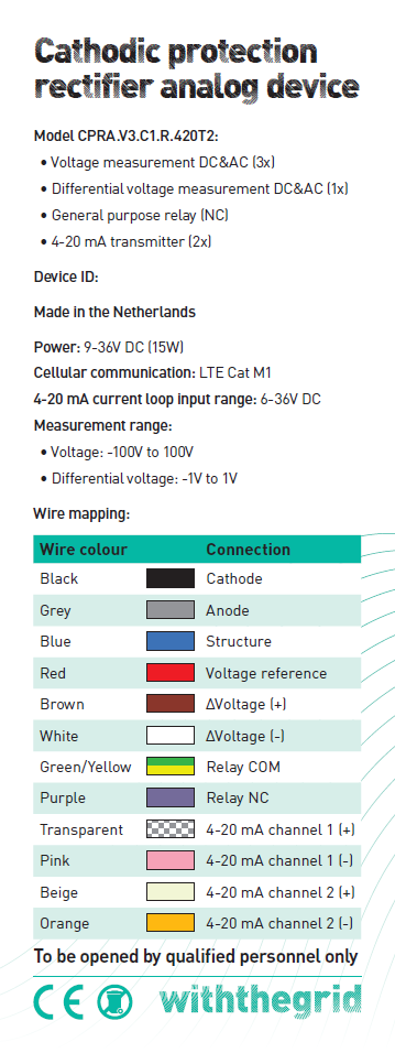
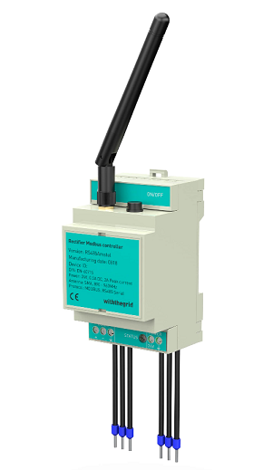
In this section, we will look at specifications of the cathodic protection analog rectifier device type. The newest version is the cathodic protection analog rectifier, model CPRA.V3.C1.R.420T2
This device is placed at rectifier locations. The required power input is 9-36V DC (15W), provided by an external power source that is connected to the mains grid (230V).
The name of the device refers to the channels it can measure, namely 3 channels for measuring voltage and 1 channel for measuring current. Also, the device contains two transmitters for 4-20 mA signal, which can be used to control rectifiers. Rectifiers that are controlled by a 0V to 10V signal, can be controlled by placing a 4-20 mA to 0-10V converter between the device and the rectifier.
The model of your device is shown on the sticker on the lid of the device. For example, this is the sticker of the newest model:
Standard commands when linking to the platform
The standard commands upon linking the device to the platform for the cathodic protection analog rectifier are:
- Calibrate device (this calibrates the inclination of the device)
- Set measurement cycle to every 5 minutes (ASAP)
- Set measurement cycle to every week or every day (sent to device ASAP, executed with a two-hour delay) (again, this final setting is dependent on how the device is delivered to the customer)
Specifications
The sticker shows some of the specifications of the cathodic protection analog rectifier device.
Measurements
The measurements of the device are taken constantly, as the device is connected to a power source, so does not need to go into sleep mode. In this regard, it differs from CP-pole devices, which only wake up to do a measurement and go into sleep mode in between.
If the device is set on an interval of - for example - one hour, the general functioning of measurements is as follows:
- At the moment of reporting (at the end of the hour) the device takes the mean (average) of all measurements during the previous period. That mean is shown as the value, so is depicted as Voltage DC or Current DC, for example.
- During the period in between teh moment of reporting, every 10 seconds measurements are performed and the measurements are added to the running statistics.
- Apart from the mean, other statistics that are reported for each quantity are minimum, maximum and standard deviation.
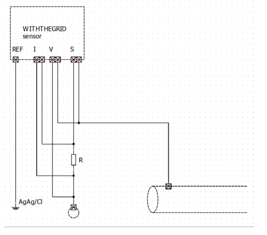
Schematic drawing for installation
The following schematic drawing is for the version without 4-20 mA output control:
Schematic drawing of cp rectifier analog device installation
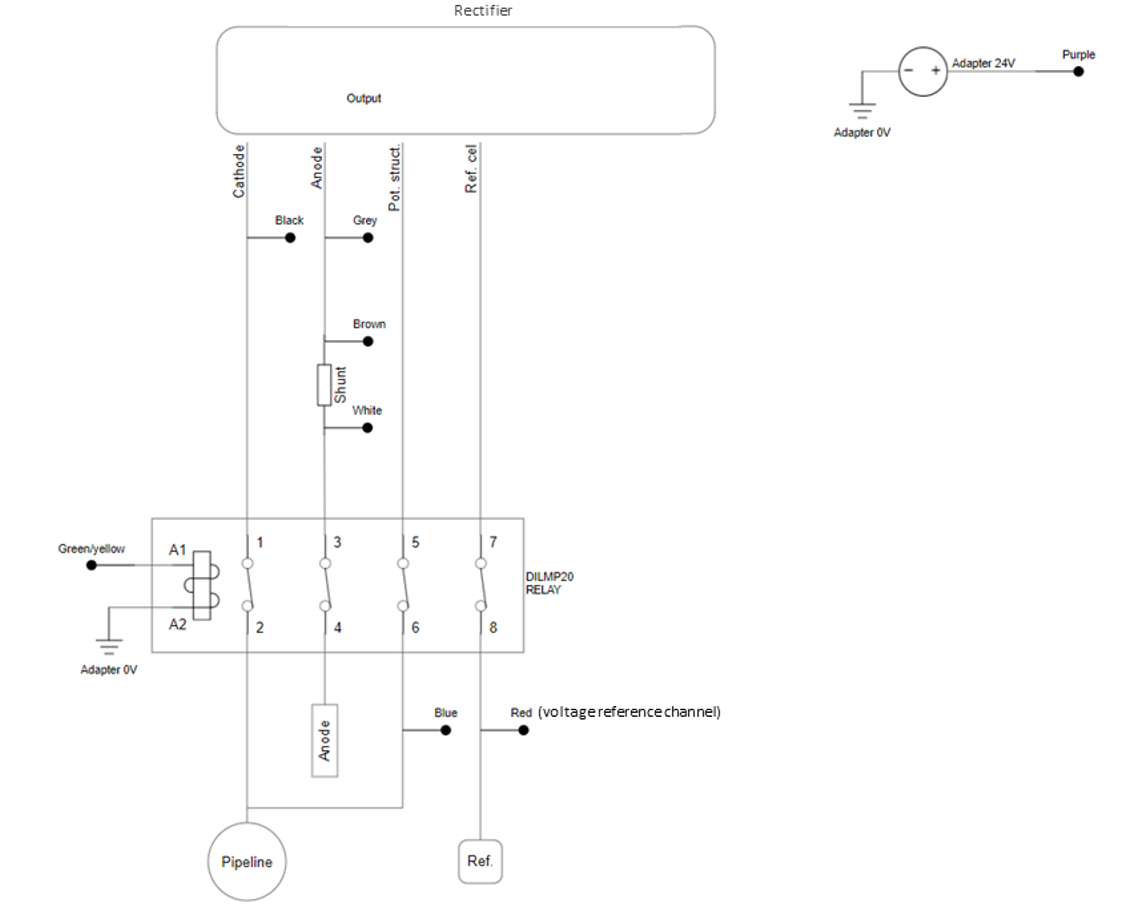
The following schematic drawing is for the version with 4-20 mA output control:
Schematic drawing of cp rectifier device including 4-20 mA output control
Relay is needed for switching
To perform the commands the cp rectifier analog device is capable of performing, such as switching and turning cathodic protection off, a relay needs to be positioned between the rectifier and the grid. This relay is controlled by the remote monitoring device.
Withthegrid does not provide the relay. It is up to the end-customer to use any relay they deem correct in terms of specifications and other factors.
One relay that we recommend and have used at multiple customers in the past is the EATON relay DILMP20 article number 276705, with a maximum current specification of 12A, see the datasheet here. If the particular rectifier functions at higher than 12A currents, another suggestion would be an EATON relay in the same series, such as the EATON DILM contactor 24VDC 32A, available for example here.
However, please be aware that if the rectifier is functioning at currents above 12A, another relay needs te be selected for that location.
Switching the rectifier off during welding activities is necessary often to protect the rectifier. A lot of built-in rectifier interrupters do not galvanically isolate the rectifier from the grid, so there is still a risk of damaging the rectifier during welding activities. Therefore, using a separate relay to switch off cathodic protection helps protect the rectifier during welding.
Commands for cathodic protection analog rectifier device
Measure once per second for 5 minutes
For 5 minutes the device will measure VDC, VAC IDC and IAC on the Anode port and VDC, VAC on the grid port every second.
Measure open circuit potential
If this command is sent to both the cp pole device and the cp rectifier analog device the time will be synchronised via the NTP server. A total of 29 V DC measurements will be executed on all grid channels every 100ms. The cp rectifier device ‘Cathodic protection analog rectifier’ will open the external relay for 2 seconds during the measurement
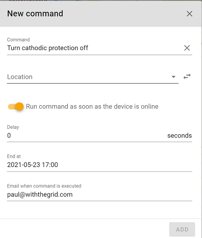
Turn cathodic protection off
Opens external relay to disable cathodic protection on the pipeline. Normal measurements will be sent during this command. End time can be specified by the user.
Measure instant off (Analog rectifier)
Opens and closes the external relay with a pre-defined On and Off-time of 12 and 3 seconds respectively and measures every half a second for 5 minutes. The device only performs the Voltage DC measurements during this command. Results are reported in a report with the name Instant off containing a specific quantity named instant off as well.
Measure once per second for 24 hours (this will drain the battery)
For 24 hours the device will measure VDC, VAC IDC and IAC on the Anode port and VDC, VAC on the grid port.
During a certain period within the 24-hour measurement the cathodic protection can be turned off. The standard setting for this is to turn off cathodic protection for 3 seconds each half hour. The period of turning cathodic protection off can be selected manually.
Measure raw signal
Will send an unprocessed buffer of the normal measurements. Used for debugging only.
Reboot sensor
Reboots the device
Configure analog rectifier
Sets the output value of the 4-20mA transmitter which is available on rev.8 hardware.
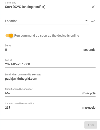
Start DCVG
Opens and closes the external relay based on user input for Off-time and On-time. Normal measurements will not be sent during this command. End time can be specified by the user.
Off Potential 12-3
Opens and closes the external relay with a pre-defined On and Off-time of 12 and 3 seconds respectively. End time can be specified by the user.
Set measurement interval
Sets the interval at which the device connects to the cloud to send reports. In this report the measurements from the previous period are sent including average, min., max. and standard deviation. This interval also determines how often the device is online to retrieve scheduled commands.
Calibrate sensor
The inclination sensor in the device will be calibrated to zero. Any change in inclination after that point will be detected by the device.
Tip on how to use: This is to be able to get notified when the device falls or when the pole or cabinet is hit by a motorized vehicle. To generate an issue when this happens, an issue trigger on the quantity inclination has to be set.
4. Cathodic protection pole device
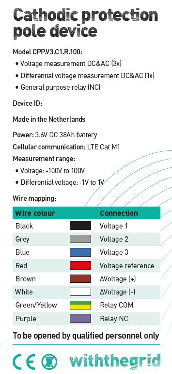
In this section, we will look at some specifics for the cathodic protection pole device type. The newest version is the cathodic protection (3x voltage, 1x current), model CPP.V3.C1.R.100.
This device is generally placed in cp poles in the field. The device runs on a battery which has a lifespan of 6 years, when measuring no more than once per day. Specific commands and higher measurement frequency may drain the battery more quickly. The battery can be replaced.
The name of the device refers to the channels it can measure, namely 3 channels for measuring voltage and 1 channel for measuring current.
The model of your device can be seen on the sticker that is on the lid of the device. Here is one example:
Standard commands when linking to the platform
The standard commands upon linking the device to the platform for the cathodic protection (3x voltage, 1x current) are:
- Calibrate device (this calibrates the inclination of the device)
- Set measurement cycle to every 5 minutes (ASAP)
- Set measurement cycle to every 6 hours (sent to device ASAP, executed with a two-hour delay)
- Set measurement cycle to every week or every day (sent to device ASAP, executed with a 7-day delay) (again, this final setting is dependent on how the device is delivered to the customer)
General information
The sticker shows some of the specifications of the cathodic protection pole device.
- Voltage measurement channels can be used for measuring the voltage on different structures
- One of the voltage measurement channels may be used for measuring the coupon. To measure coupon, it is important that when linking the device, the settings of this port are changed to switch the relay before measurement. For example, if the voltage 3 channel is used for measuring coupon, setting that port looks like this:
The coupon channel will be measured after 500 ms in the standard settings. This setting can be found under Properties on the location, in the field Time delay after opening the relay:
.B095e-sQ_ZR8Umf.PNG)
- The differential voltage channel is used to measure current. For this, the voltage over a shunt is measured. For current measurements to be displayed in the user interface, in graphs and reports, first the shunt value has to be entered on the location:
Specifications
| Product codes | Model CPP.V3.C1.R.100 |
|---|---|
| Channels | 3X DC & 3X AC voltage 1X AC & 1X DC current |
| Range and accuracy | Model CPP.V3.C1.R.50 AC+DC current: ± 10mA-20A @ max. ± 2.5% + 1 digit resolution AC+DC current: ± 10mA-20A @ max. ± 2.5% + 1 digit resolution |
| Impedance | >20 MOhm |
| Frequency | 16 2/3 – 100 Hz (digitally filtered) |
| Switch accuracy | +/- 1 ms |
| Time synchronization | NTP |
| Coupon measurement | On potential (AC+DC), Off potential (AC+DC), Current AC, Current DC |
| Measurement interval | adjustable; 1x/5min to 1x/week |
| Norms | Conform the EN-norms 13509 |
| Power | Battery 38Ah, 6 years with 4X / day measurement |
| Communication protocol | LTE-M Cat1 |
| Encryption | End-to-end DTLS encryption |
| Firmware over the air | Yes |
| IP-rating | 65 |
| Dimensions | 250 x 80 x 70 mm |
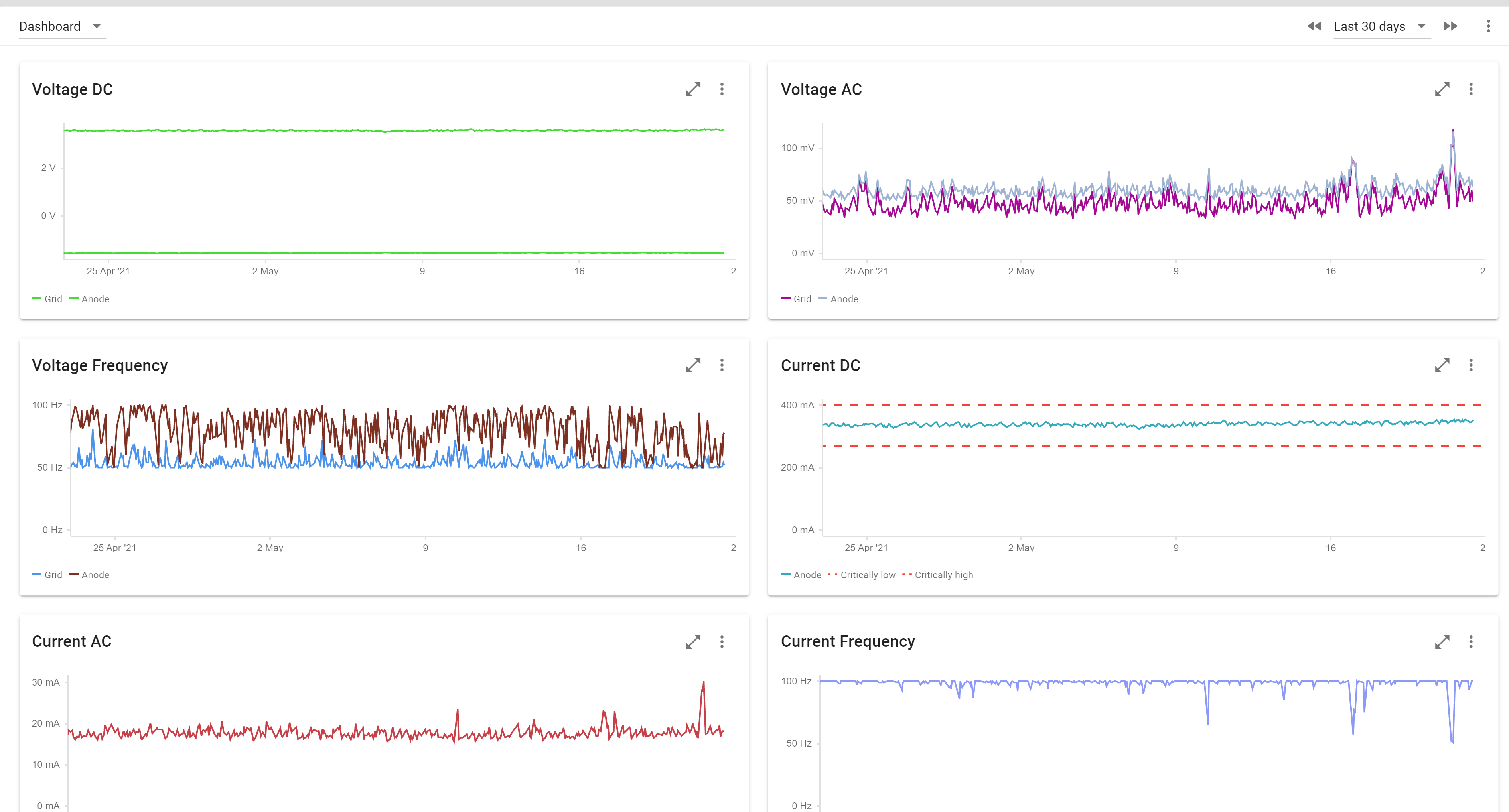
Cathodic protection measurements
Once you have installed the device you will automatically record cathodic protection measurements in your monitoring environment.
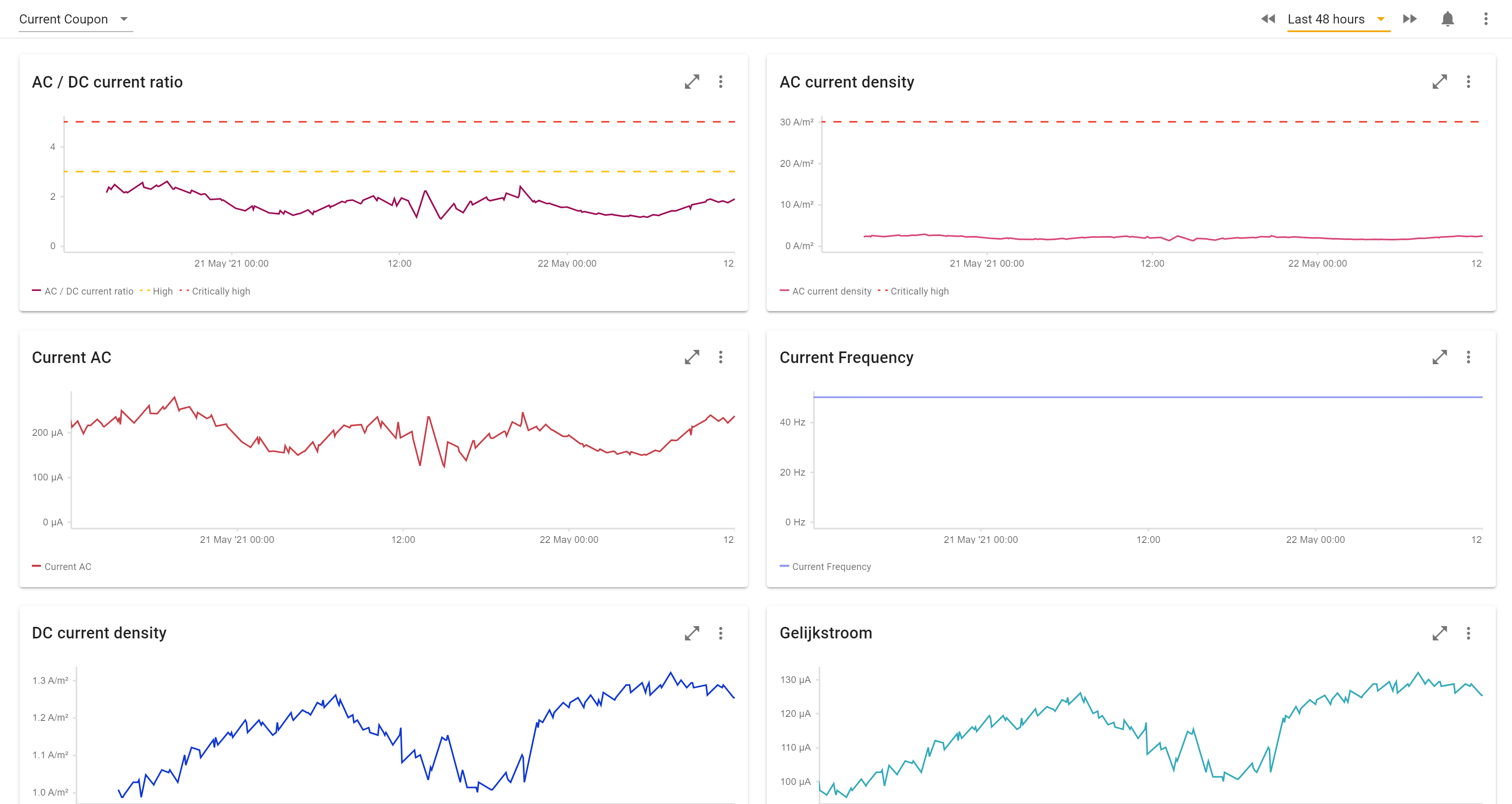
Coupon measurements
For locations with a coupon additional AC corrosion risk measurements are carried out. In the example below you see an automatic calculation of the AC and DC current density.
Off-potential measurements
It is also possible to create off-potential measurements by having the rectifier switch (e.g. 10s on/2s off, but this is configurable). After this command is executed all locations with a remote monitoring unit and that linked to that rectifier shall simultaneously make 30 measurements at 100ms intervals. The result is a depolarization curve as shown in the image below.
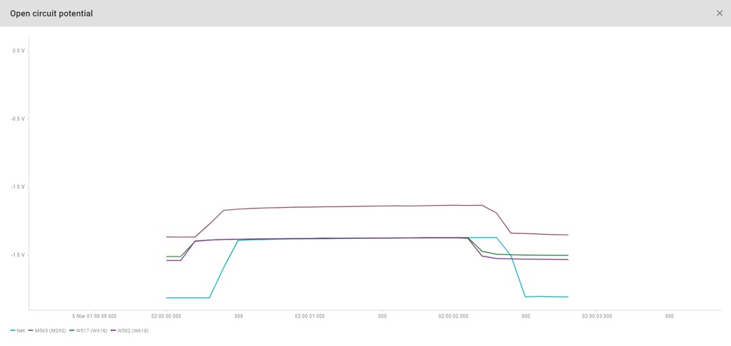
Depending on the requirement it is possible to automatically select 1 measurement and regard that as the off potential measurement. In that way it is possible to set a issue trigger on the off potential. Secondly, it is possible to automatically schedule these measurements with a fixed interval. For example: every 2 weeks.
Rectifier on/off and switching
In addition to off potential measurements the rectifier can also be switch off for works or other activities such as DCVG measurements.
AC Corrosion risk determination
The Cathodic Protection (3x voltage, 1x current) is able to perform an AC corrosion risk determination when a coupon is installed with a shunt in series. If, in the location properties, the Shunt resistance and Coupon area fields are filed in, a risk factor will be determined. The quantities DC current density, AC current density and AC/DC current ratio are calculated based on the Coupon area, Current DC and Current AC. The AC/DC Current ratio has default issue triggers of 3 (High) and 5 (Critically high).
Schematic drawing for installation
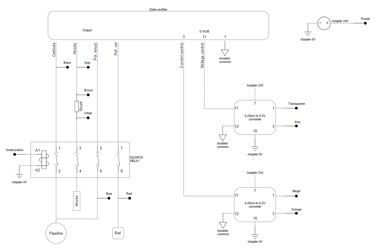
The schematic drawing below may function as a guide to the installation of the device. In this drawing:
- ‘I’ stands for current and corresponds to the brown and white wires
- ‘V’ stands for voltage and corresponds to the black, grey and blue wires (grey may be red on certain devices, check the device information on the sticker)
- ‘S’ stands for switch / relay and corresponds to the yellow/green and purple wires
Schematic drawing for installation of CP-pole device
Commands for cathodic protection pole device
Set measurement interval
Choose between a range of intervals in which the sensor will measure and report. This command will determine the frequency at which the sensor comes online. Beware that higher frequencies will also drain the battery faster.
Calibrate sensor
The inclination sensor in the device will be calibrated to zero. Any change in inclination after that point will be detected by the device.
Tip on how to use: This is to be able to get notified when the device falls or when the pole or cabinet is hit by a motorized vehicle. To generate an issue when this happens, an issue trigger on the quantity inclination has to be set.
Measure open circuit potential
If this command is sent to both the Cathodic protection (3x voltage, 1x current) and the Cathodic protection analog rectifier, the time will be synchronized via the NTP server. A total of 29 VDC measurements will be executed on all active channels every 100ms. The Cathodic protection analog rectifier will open the external relay for 2 seconds during the measurements.
Start DCVG
This command allows for switching the internal general-purpose relay of the Cathodic protection (3x voltage, 1x current). This is only useful if the sensor is used on a passive CP grid and the anode is connected in series with this relay. If so, this command can be used to perform manual DCVG measurements. Since the time that the switch is ON and the time the switch is OFF can be changed in the command prompt, other switching operations can also be performed.
Measure instant off
The internal general-purpose relay will switch to the ON position for 12 seconds and to the OFF position for 3 seconds for a total duration of 5 minutes. During this time, every 500ms a VDC measurement is performed per chosen active channel. This command is useful when connecting the Cathodic protection (3x voltage, 1x current) to a passive CP grid and the anode is connected in series with this relay. This command might also be used if a coupon is connected in series with this relay. This allows for instant-off measurement on the connected coupon.
Measure once per second for 24 hours (this will drain the battery)
The Cathodic protection (3x voltage, 1x current) will measure once every second for 24 hours on all channels. This means it will measure VDC and VAC on the voltage channels, and IDC and IAC on the current channel. Please note that this command drains the battery very fast, so please only use when a full battery has been connected recently and you are willing and able to replace that battery after performing one of these commands!
Measure stray current
The Cathodic protection (3x voltage, 1x current) will measure every 500ms on the Current (I) channel and a chosen active voltage channel. This command will only measure and report VDC and IDC measurements. There is an option to enable the internal general-purpose relay to switch during the measurements. Its default setting is to switch open for 3s every hour. The total duration can the manually set, and is default set to 24 hours.
5. Amstel rectifier controller device
This modbus remote monitoring device controls Amstel rectifiers. This enables direct control of the Amstel rectifier giving the ability to set the output voltage and current.
Amstel rectifier controller device
Standard commands when linking to the platform
The standard commands when linking to the platform are Set measurement interval.
Specifications
| Model | Controller for Amstel rectifier |
|---|---|
| Versions | Rev. 1 and Rev. 2 |
| Communication protocol | Modbus |
| Cellular communication | 2G or LTE-M Cat1 |
| Time synchronization | NTP |
| Measurement frequency | Adjustable; 1x / 5 min to 1x / week |
| Encryption | End-to-end DTLS encryption |
| Firmware over the air update | Yes |
| IP rating | no |
| Power supply | 24 VDC |
| Dimensions | 90 x 57 x 53 mm |
Schematic drawing for installation
n/a
Commands for Amstel rectifier controller device type
Start DCVG (Amstel rectifier)
Two grid relays and the control relay for the potential of the selected rectifier will open and close in the selected pattern. The relays of the cathode, anode and rectifier reference electrode will remain closed. The standard settings for the Amstel are closed for 4 seconds and open for 2 seconds per cycle.
Measure open circuit potential
If this command is sent to both the cp pole device and the cp rectifier analog device the time will be synchronised via the NTP server. A total of 29 V DC measurements will be executed on all grid channels every 100ms. The cp rectifier device ‘Cathodic protection analog rectifier’ will open the external relay for 2 seconds during the measurement
Configure Amstel rectifier
This command can be used to change the settings of the Amstel rectifier
Turn cathodic protection off
Opens external relay to disable cathodic protection on the pipeline. Normal measurements will be sent during this command. End time can be specified by the user.
Calibrate sensor
The inclination sensor in the device will be calibrated to zero. Any change in inclination after that point will be detected by the device.
Tip on how to use: This is to be able to get notified when the device falls or when the pole or cabinet is hit by a motorized vehicle. To generate an issue when this happens, an issue trigger on the quantity inclination has to be set.
6. Measurement handling while commands are running
Because the cp-analog-rectifier device influences the power of the cathodic protection grid, some commands sent to this device can impact the measurements of cp-pole devices connected to the same grid as well as the measurements of the cp-analog-rectifier device itself. This can cause issues to trigger on these devices, even though the measurements are expected due to the commands given.
To counter this, the reports of both types of cp devices have four different ways in which they can handle measurements:
- Standard: The measurements are visible in the normal graph and can be trigger issues.
- Ignore issue triggers: The measurements are visible in the normal graph, but issue triggers are ignored. therefore, these measurements do not trigger issues.
- Delete measurements: The measurements are deleted from (or rather, not pushed to) the environment and are therefore not visible in the normal graph and cannot trigger issues.
- Push to other quantity: The measurements are pushed to another quantity and are therefore visible in a separate graph and can only trigger issues linked to this separate quantity.
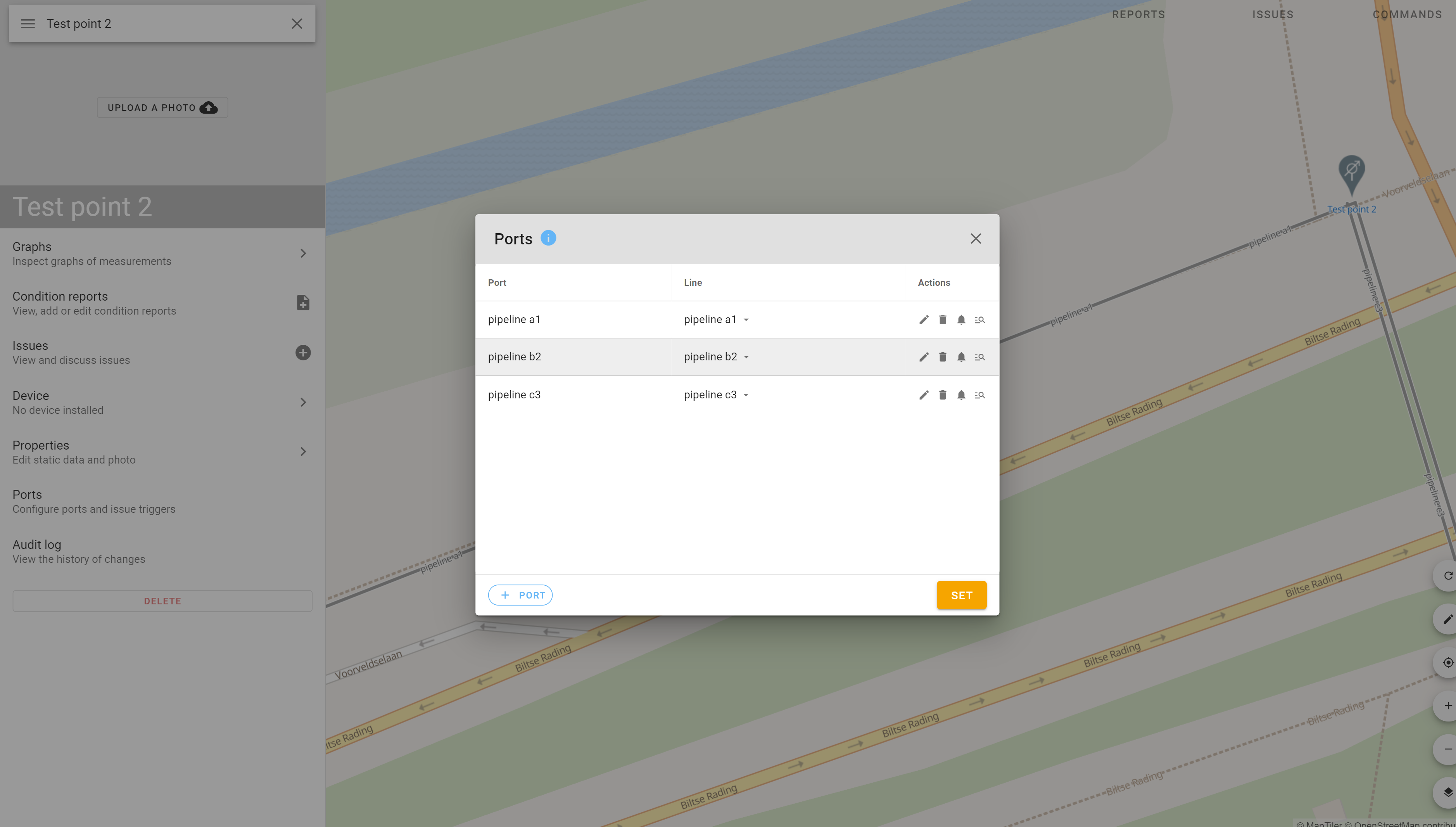
Linking cp devices
The cp-pole device can be connected to a different grid on each voltage or current port. Therefore, it is the individual port of the cp-pole device that is linked to a cp-analog-rectifier device.
To connect a cp-pole port to the right cp-analog-rectifier device, select the location of the cp-pole device, click on ‘Ports’ in the left panel, press ‘edit’ on the voltage or current port, and fill in the name of the connected cp-analog-rectifier location in the ‘Link to rectifier location’ form-field.
Measurement handling settings
The measurement handling is set as follows:
| Command | Cp-analog-rectifier | Cp-pole |
| Measure instant off | Standard | Ignore issue triggers |
| Measure open circuit potential | Standard | Ignore issue triggers |
| Off potential 12-3 | Standard | Ignore issue triggers |
| Start DCVG | Standard | Delete measurements |
| Turn cathodic protection off | Push to other quantity | Ignore thresholds |
How the measurements are handled for each port, and how each port is connected to a rectifier location can be seen on each port in the form fields for that port.
7. Integrations
Historic measurement data
In case you would like to import a set of historic measurement data we can help you with that. Ofcourse you can do it yourself by using our friendly API. However if you would like us to do it, we are happy to help. Please contact us at: info@withthegrid.com
Integrating with GIS
Another possibility is to integrate with your existing GIS system. The advantage is that all locations and pipelines from your GIS are synchronized with Withthegrid. This avoid duplicate datasets and ensures data consistency. There are many technical ways in which this is possible and this depends on the type of GIS system currently used. Please contact us to discuss options.
Exporting data
All data can be exported in 3 manners
8. Questions
If you have any questions, would like to order CP remote monitoring devices please contact us: info@withthegrid.com